As a large proportion of the inductive or lagging current on the supply is due to the magnetizing current of induction motors, it is easy to correct each individual motor by connecting the correction capacitors to the motor starters. With static correction, it is important that the capacitive current is less than the inductive magnetizing current of the induction motor. In many installations employing static power factor correction, the correction capacitors are connected directly in parallel with the motor windings. When the motor is Off Line, the capacitors are also Off Line. When the motor is connected to the supply, the capacitors are also connected providing correction at all times that the motor is connected to the supply. This removes the requirement for any expensive power factor monitoring and control equipment. In this situation, the capacitors remain connected to the motor terminals as the motor slows down. An induction motor, while connected to the supply, is driven by a rotating magnetic field in the stator which induces current into the rotor. When the motor is disconnected from the supply, there is for a period of time, a magnetic field associated with the rotor. As the motor decelerates, it generates voltage out its terminals at a frequency which is related to it's speed. The capacitors connected across the motor terminals, form a resonant circuit with the motor inductance. If the motor is critically corrected, (corrected to a power factor of 1.0) the inductive reactance equals the capacitive reactance at the line frequency and therefore the resonant frequency is equal to the line frequency. If the motor is over corrected, the resonant frequency will be below the line frequency. If the frequency of the voltage generated by the decelerating motor passes through the resonant frequency of the corrected motor, there will be high currents and voltages around the motor/capacitor circuit. This can result in severe damage to the capacitors and motor. It is imperative that motors are never over corrected or critically corrected when static correction is employed.
Static power factor correction should provide capacitive current equal to 80% of the magnetizing current, which is essentially the open shaft current of the motor.
The magnetizing current for induction motors can vary considerably. Typically, magnetizing currents for large two pole machines can be as low as 20% of the rated current of the motor while smaller low speed motors can have a magnetizing current as high as 60% of the rated full load current of the motor. It is not practical to use a "Standard table" for the correction of induction motors giving optimum correction on all motors. Tables result in under correction on most motors but can result in over correction in some cases. Where the open shaft current can not be measured, and the magnetizing current is not quoted, an approximate level for the maximum correction that can be applied can be calculated from the half load characteristics of the motor. It is dangerous to base correction on the full load characteristics of the motor as in some cases, motors can exhibit a high leakage reactance and correction to 0.95 at full load will result in over correction under no load, or disconnected conditions.
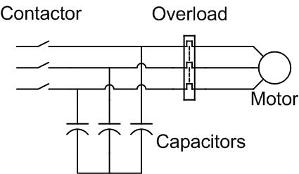
Typical static PFC application
Static correction is commonly applied by using one contactor to control both the motor and the capacitors. It is better practice to use two contactors, one for the motor and one for the capacitors. Where one contactor is employed, it should be up sized for the capacitive load. The use of a second contactor eliminates the problems of resonance between the motor and the capacitors.
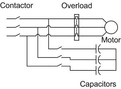
Improved static PFC application
Inverter
Static Power factor correction must not be used when the motor is controlled by a variable speed drive or inverter. The connection of capacitors to the output of an inverter can cause serious damage to the inverter and the capacitors due to the high frequency switched voltage on the output of the inverters.
The current drawn from the inverter has a poor power factor, particularly at low load, but the motor current is isolated from the supply by the inverter. The phase angle of the current drawn by the inverter from the supply is close to zero resulting in very low inductive current irrespective of what the motor is doing. The inverter does not however, operate with a good power factor. Many inverter manufacturers quote a cos Ø of better than 0.95 and this is generally true, however the current is non sinusoidal and the resultant harmonics cause a power factor (KW/KVA) of closer to 0.7 depending on the input design of the inverter. Inverters with input reactors and DC bus reactors will exhibit a higher true power factor than those without.
The connection of capacitors close to the input of the inverter can also result in damage to the inverter. The capacitors tend to cause transients to be amplified, resulting in higher voltage impulses applied to the input circuits of the inverter, and the energy behind the impulses is much greater due to the energy storage of the capacitors. It is recommended that capacitors should be at least 75 Meters away from inverter inputs to elevate the impedance between the inverter and capacitors and reduce the potential damage caused.
Switching capacitors, Automatic bank correction etc, will cause voltage transients and these transients can damage the input circuits of inverters. The energy is proportional to the amount of capacitance being switched. It is better to switch lots of small amounts of capacitance than few large amounts.
Solid State Soft Starter
Static Power Factor correction capacitors must not be connected to the output of a solid state soft starter. When a solid state soft starter is used, the capacitors must be controlled by a separate contactor. The capacitor contactor is only switched on when the soft starter output voltage has reached line voltage. Many soft starters provide a "top of ramp" or "bypass contactor control" which can be used to control the power factor correction capacitor contactor.
If the soft starter is used without an isolation contactor, the connection of capacitors close to the input of the soft starter can also cause damage if they are switched while the softstarter is not drawing current. The capacitors tend to cause transients to be amplified, resulting in higher voltage impulses applied to the SCR’s of the soft starter, and due to the energy storage of capacitors, the energy behind the impulses is much greater. In such installations, it is recommended that the capacitors be mounted at least 50 meters from the soft starter. The elevated the impedance between the soft starter and the capacitors reduces the potential for damage to the SCR’s.
Switching capacitors, Automatic bank correction etc, will cause voltage transients and these transients can damage the SCRs of Soft Starters if they are in the Off state without an input contactor. The energy is proportional to the amount of capacitance being switched. It is better to switch lots of small amounts of capacitance than few large amounts.
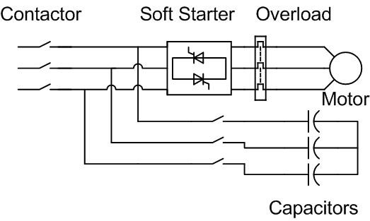
Static PFC applied to a soft starter