Warning: Due to the risk of electrical shock due to energy stored
in capacitors they should be handled by properly trained personnel.
Occasionally, such as during annual maintenance shut-downs, it is important to test your capacitor banks to ensure they are operating at peak efficiency. Besides general cleaning and checking, making sure all the nuts and bolts of the system are in good working order, perhaps the most important item in the unit is the condition of the capacitors. Over time and use, like everything else, man-made capacitors will degrade and eventually need to be replaced.
You can test the capacitors in two ways. With power “OFF” and then with power “ON”.
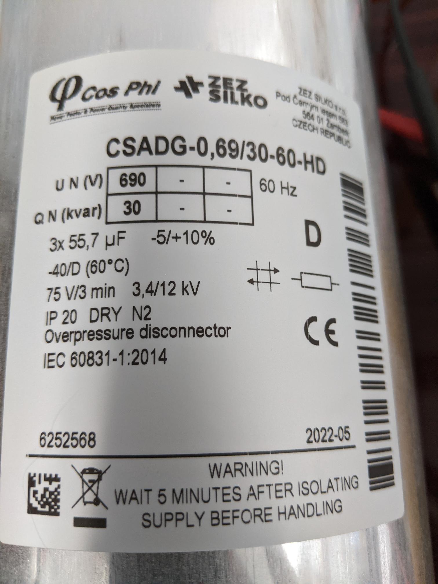
For the purpose of this article, we are going to use the nameplate from a capacitor below as our reference.
 30kVAR, 690V Capacitor Namplate
From the name plate we learn the following pertinent electrical ratings of the capacitor:
Voltage Rating: 690V
kVAR Rating: 30kVAR
Connection Type: Delta
Capacitance: 3 x 55.7uF
First, we need to determine the type of connection we are working with. Is it a Wye connected capacitor or a Delta connected? We also need to know the type of connection to know which formulas are used as our baseline for electrical measurements.
In this case it is a Delta connected capacitor, indicated by the “D” on the nameplate. Some manufacturers may use the electrical symbol for Delta instead of a “D”.
In our first test, we are going to assume that the capacitor is “OFF”. We test this capacitor by measuring the capacitance of the capacitor. This is done using a capacitance meter (some multi-meters have this function built in).
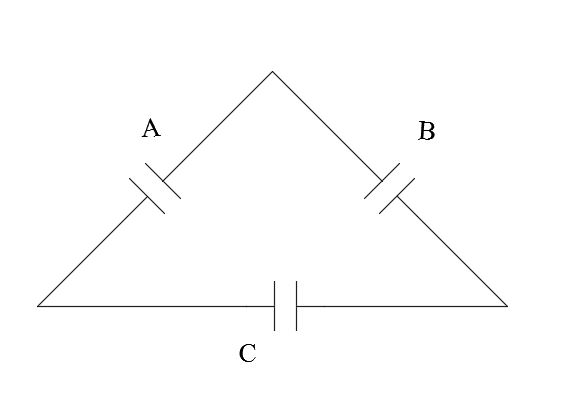
 Delta Connected Capacitor
Looking at the image of a delta connection above, three individual capacitors makeup the capacitor assembly. If you place the meter leads across any two terminals, it will be measuring a circuit consisting of two capacitors in series with a third capacitor connected in parallel.
Two capacitors in series have half the capacitance of one capacitor. While paralleling the caps will use the sum of two groups.
In this case, the two in series will be 27.85uF. Then 27.85 + 55.7 = 83.55uF -5 to +10%
Any combination of the three terminals should have the same measurement result. It is not uncommon to have failed segments in the capacitor assembly.
If the capacitor assembly is wye connected. You will only measure the series connected two elements. In this case you would measure 27.85uF for any combination.
As long as we get the desired measurements the capacitor is in optimal condition. If the measurements fall outside of the expected range, they should be replaced before further deterioration occurs.
In the second test where the step is powered “ON”, you can use an amp clamp meter to measure the current of the capacitor.
Using the formula kVAR = I x E x 1.73 we solve for current:
I = (kVAR / E) / 1.73
Note: In this case the capacitor is rated 690 volts so an extra step is required. We need to determine the kVAR rating at 600V as that is the voltage of the line the capacitor is operating on. Using capacitors with a higher rated voltage will extend the life of the capacitor but there is a derating factor on the kVAR supplied.
We use the following formula to make that determination:
kVAR = (System Voltage/Capacitor Voltage)
2 x 690V capacitor kVAR rating
kVAR = (600V / 690V)
2 x 30kVAR
kVAR @ 600V = 22.68kVAR
Now that we know the kVAR rating at 600V we can calculate the single-phase current of the capacitor that we need to measure with our amp clamp meter.
I = (kVAR / E) / 1.73
I = (22680 / 600) / 1.73
I = 21.85A
If we put our amp clamp meter on each phase, we should measure 21.85A (-5 + 10%)
It is normal over time for the capacitance to deteriorate as the capacitor ages, resulting in a drop in current. There will be a point at which the capacitor bank can no longer achieve the desired power factor. To ensure optimal performance from your capacitors, we recommend that you replace them when they fall outside of their electrical parameters.


